Building a Photographic Baseline for Expansion Joints
A photographic baseline makes future joint inspections easier to compare. Take repeatable views at handover and connect them to fixed locations, so later teams can distinguish a new change from the original condition.
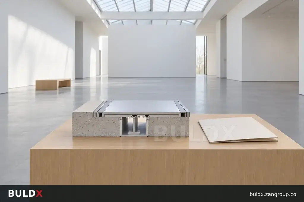
Selection considerations
Choose overview and close-up positions for each joint run. Include intersections, terminations and transitions between finishes. Record the camera direction and location on the plan. Similar-looking corridors should not be documented with unlabelled photographs that cannot be assigned to one run.
Photograph the accepted visible condition and any accessible details required by the inspection plan. Include a scale where a dimensional observation matters. Do not estimate movement capacity or concealed fixing quality from the finished surface alone; retain the corresponding inspection records separately.
Store the photos with the product codes, approved drawing revision and handover date. For later inspections, use the same positions where possible and document changes in loading or nearby finishes. A baseline supports maintenance decisions, but it does not replace the agreed inspection criteria.
Before you specify or order
- Select repeatable photo positions
- Include junctions and terminations
- Link photos to drawing revisions
- Retain hidden-work inspection records separately
Relevant BULDX catalogue examples
These records illustrate the product types discussed. Compare the full specifications before selecting; listing here does not establish project suitability or make the items interchangeable.

BDX-EJ-FL-RF-100-45-310-P30-N60-AL · Catalogue geometry reference; a family illustration may be shared by variants. Consult the exact selected drawing for variant dimensions and assembly requirements.| Product and code | Selected catalogue fields |
|---|---|
BDX-EJ-FL-RF-100-45-310-P30-N60-ALRecessed Seismic Floor Joint · 100 mm opening · 45 mm heightSeismic Floor Joints |
|
BDX-EJ-FL-RF-100-70-352-P40-N50-TPERecessed Seismic Floor Joint · 100 mm opening · 70 mm heightSeismic Floor Joints |
|
BDX-EJ-FL-RF-150-45-360-P50-N100-ALRecessed Seismic Floor Joint · 150 mm opening · 45 mm heightSeismic Floor Joints |
|
Common question
Can photographs replace installation inspection records?
No. Finished views may not show concealed supports, fixings or barriers, which need their own records.
References and scope
Product fields are from the BULDX catalogue. Confirm the current selected drawing, supporting performance documents and approved project detail before ordering. External references, where listed, provide background guidance and do not certify these products.